Brand:-
Model:HEM-01
MOQ:-0 -
We offer Hall Effect in metals, it enables the charge carrier concentration and mobility to be determined by experiment. Direction of the Hall Voltage in silver indicates negative charge carriers, which is in agreement with concepts of the model of the ‘free electron gas‘. Limitations of this model are shown by the so called ‘abnormal Hall Effect’ of tungsten. The experiment carried out under identical conditions for tungsten show the Hall Voltage to have about same magnitude but opposite direction as in silver.
This can be explained by the ‘Energy Band diagram’. The tungsten atom has …….5s2 5p6 5d4 6s2 electronic structure. When the atoms come close together to form the solid, the close lying states 5d and 6s broaden into bands, with s band broadening considerably more than the d band. This is because of the larger size of the s orbital. The figure schematically shows the allowed energies as a function of the interatomic distance. The number of allowed states is ten per atom in the d band and two in the s band. In tungsten there are six electrons to be shared between these two bands. The result is that at the interatomic distance in tungsten there are holes in the d band and electrons in the s band, making tungsten
predominantly a hole conductor.
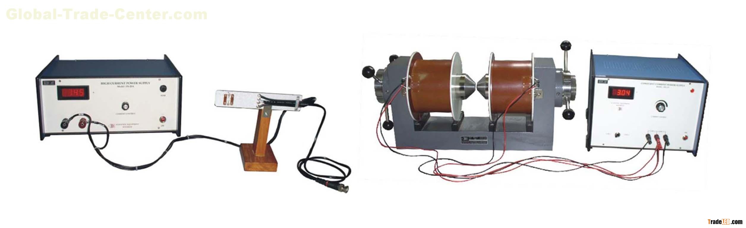
The apparatus consists of the following:
a) Hall Probe-Silver (HP-Ag)
Material: Silver Strip (8 x 6 x 0.05 mm)
Contacts: Press type for current
Spring Type for Voltage
Hall Voltage: ~17 µV/10A/10KG
b) Hall Probe-Tungsten (HP-W)
Material: Tungsten Strip (8 x 6 x 0.05 mm)
Contacts: Press type for current
Spring Type for Voltage
Hall Voltage: ~15 µV/10A/10KG
c) High Current Power Supply, Model PS-20A
Range: 0-20A continuously variable
Accuracy: ±0.5%
Regulation: ±0.5% for ±10% variation of mains
Display: 3½ digit, 7 Segment LED
d) Digital Microvoltmeter, DMV-001
Range: 1mV, 10mV, 100mV, 1V & 10V with 100% over-ranging.
Resolution: 1μV.
Accuracy: ±0.2%.
Stability: Within ±1 digit.
Input Impedance: >1000MΩ (10MΩ on 10V range).
Display: 3½ digit, 7 segment LED with auto .polarity and decimal indication
e) Electromagnet, Model EMU-75T
Pole Pieces: 75mm tappered to 25mm
Mag. Field: 17KG ±5% at 10mm airgap
Energising Coils: Two of approx. 13W each
Power: 0-90Vdc, 3A, for coils in series
0-45Vdc, 6A, for coils in parallel
f) Constant Current Power Supply, Model DPS-175
g) Gaussmeter, DGM-202
The experiment is complete in all respect.


