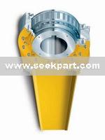
High precision NJD(DSN) low speed backstop bearing
This type of backstop bearing is located using a bearing in which several shaped wedges are arranged in the raceway formed by inner race and outer race in a certain pattern so that it operating stably the outer race is connected with two ends covers, while the end covers are connected with the antirotation arm in to an integral part through pins and the antirotation arm is limited by the fixed antirotation seat. When the motor operates normally, the backstop make the wedges defect by a certain angle through mechanics principle using the special geometry of the wedges so as to be in light contact with inner and outer race, thus reducing the coefficient of friction and improving the service life of the backstop . When the main motor needs to be shut down, the inner race of the backstop reverses under action of gravity of elevated material to drive the wedges to deflect and bring the inner and outer race of the holdback to be wedged into an integral part so as to effectively prevent the motor from reversing. Therefore, this type of holdback is the most ideal non-reversing protector for conveying equipment such as large belt conveyor, bucket elevator etc.
2 Service environments
The ambient temperature for backstop operation is -20~50°C,when the backstop is running, it will generate certain heat, so the ambient environment should be well ventilated ,the temperature of the backstop running at allowable highest speed can reach 80°C ,in this case it is required to check the effect on the motor equipment and take appropriate temperature reduction measures , if necessary .When the ambient service temperature exceeds 30°Cor when it operates in open air , effective protective measures should be taken(for example, use ventilating equipment or cooling equipment etc.) Around the backstop it is not allowed to place corrosive chemicals for fear of damaging the holdback seal.
3 Model designation of the backstop bearing
NJD(DSN) Installation hole diameter (mm) Rotational direction of inner race, when viewing from end face of shaft extension, the inner race rotates clockwise, marked as “S” on the contrary, marked as “N” Specification code (1%N•m of rate backstop moment) Low-speed backstop Example: NJD backstop with clockwise rotational direction inner race, the specification of 330 and the installation hole diameter of 300mm the model is NJD-S-300.
4 External installation dimensions and main technical parameters of low-speed backstop bearing (Table 1) Table 1
Notes: (1) It is recommend to adopted F7/h6 for the fit between the backstop hole and shaft (see Table 2)(if the user selects other fit, he should indicate this in the contract) (2) The backstop bearing hole and shaft are mainly connected with flat key, and the dimension of key and keyway should satisfy the provision of GB/T1095-1979 (see Table 2). (3) The length of shaft extension of the holdback should be equal to the length of inner race of the holdback as for as possible, its min, length should not be less than 5/6 length of inner race so as to ensure the strength of shaft extension and key.
Tolerance of shaft ,hole and keyway of the backstop bearing (Table 2)
Notes: if the hole diameter of backstop bearing is bigger than 500mm ,please consult the dimension of keyway with the technical development center of our Group.
5 Selection of the backstop bearing
The backstop bearing is installed on the lower belt shaft of the reducer or shaft of dirive pulley (see the arrangement of the backstop bearing for detail),calculate the required backstop bearing Tc according to actual operating condition, and Tc should be less than or equal to rated backstop bearing moment Te ( i.e. T c≤ Te). Where: Te-rated backstop bearing moment (N•m) Tc-calculated backstop bearing moment (N•m)
P— backstop bearing power ( kW) P1—required power for idle horizontal operation (kW) P2—required power for load horizontal operation (kW) P3—required power for vertical elevation (kW) f—drag coefficient for simulated operation of belt conveyor ,generally take f=0.012-0.03 W—weight for the operation section other than the material (kg/m) W= weight of rotary section of carrying idler/ space of carrying idlers + weight of rotary section of idle strand carrying idler/ space of idles strand carrying idlers +2×belt weight of unit length Q—max. conveying capacity (t/h) V—conveyor speed (m/min) L—horizontal distance between head pulley and tail pulley (m) L0=0.77931/f-0.006436 + 15.93Lo—correction factor for center-to-center distance between head and tail pulleys(m) Lo=0.77931/f-0.006436 + 15.93(m) H—total elevation height of material (m) Ko—correction value of drag coefficient for simulated operation of conveyor Ko=0.4~1 (take small value for Ko when take big value for f) N—shaft speed of backstop bearing (r/min) St—take St=1.5 for the coefficient of operating condition of the backstop bearing in case of three times per day, and take St=2.0 in case of over three times per day. Notice: according to the service environment or downhole service requirements, the coefficient of operating conditions of the backstop bearing S1 value should be greater than 2~4.
5.1 According to the moment Te of the backstop bearing , select backstop bearing specification according to Table 16, it is required that Tc≤Te. 5.2 Determine the diameter of installation hole of the backstop bearing according to dimensions of shaft extension. 5.3 Determine rotational direction of the backstop bearing ,observe in face of end face of shaft extension, if the shaft extension rotates clockwise, the rotation code of inner race is “S”, on the contrary , the rotation code is “N”. 5.4 There are multiple options for installation types of the backstop bearing are (see Fig.5), according to the position of service site, installation with pin hole and installation without pin hole can be selected, and for vertical installation, we recommend the installation without pin hole. For inclined and horizontal installation, we recommend the installation type with pin whole .Vertical installation should be indicated in the order, and other types of installations need to be indicated in the order.
6 Arrangement of the backstop bearing
The backstop bearing can be installed on the output shaft of reducer of the motor , or installed on the pulley shaft of the motor, for the motor for multiple simultaneous drivers, the backstop bearing also can adopt multi- backstop bearing installation (refer to the figure below), but the uneven load factor of the backstop bearing should be considered (see Table 3). Uneven load factor of multiple backstop bearing (Table3)
7. Installation of the backstop bearing
7.1 Installation type of the backstop bearing 7.2 Instructions for backstop bearing installation 7.2.1 Before installation, be sure to verify if the speed of the shaft fitted with the holdback falls within the range of max. speed allowed for holdback. 7.2.2 Before installation, be sure to check if the rotational direction of the shaft conforms to that of inner race of the holdback. 7.2.3 During the installation, it is only allowed to apply pressure to the inner race of the holdback, in order to avoid damaging the end of inner race, please knock it with wooden hammer and red copper bar, never knock end cover of the holdback, and it is strictly prohibited to heat the inner race. 7.2.4 When install ting the holdback, it is only allowed to use flat key instead of wedge key, and between the key and keyway there should be a clearance. 7.2.5 During the installation, compress the inner race of holdback with closure on the shaft end (the closure is prepared by user). 7.2.6 Generally the lower end anti-rotation big arm of the holdback is fixed between two stops of the ant rotation seat, and it should be ensured that the holdback is able to move freely in axial direction, between the stop and force arm there should be a clearance of 3~5mm, it can also be fixed with pin shaft, and it should be ensured that a clearance of 3~5mm should to kept between the pin shaft and hole, the antirotation seat is prepared by the user.
8. Lubrication and maintenance of the backstop bearing 8.1 NJD11-NJD40 holdback adopts 2# general lithium base grease for lubrication, the holdback has been filled full of lubricating grease upon delivery, so it is needed to fill the grease before using the holdback, but it is needed to make up small amount of 2# general lithium base grease once every three months. 8.2 NJD50-NJD1750 holdback generally adopts thin oil lubrication, and also can adopt the mixture of 2# general lithium base grease and SJ5W/40 engine oil or other automobile engine oil of the same performance after uniform blending in order to prevent leakage under special environment ,this holdback has been filled full of the oil upon delivery without the need to add oil before using it, but it is needed to make up a small amount of the grease of the same blend once every months(there are instructions when the product is delivered). 8.3 The holdback adopting thin oil lubrication should meet the following provisions: The product is not filled with oil upon delivery, before using it, it is required to fill SJ5W/40 engine oil or other automobile engine oil of the same performance according to the requirements. The filling amount of the graphite or any other extreme pressure additive that improves lubrication performance for lubrication, otherwise ,this will cause slip of the holdback. 8.4 Cover of the holdback there are oil holes or oil cups used for oil filling. 8.5 On the end cover of the holdback there are provided a screw plug(vent) and oil level indicator and on the bottom end of the end cover there is provided a oil drain hole etc. 8.6 One year after operation of the holdback, if there happens such phenomenon as abnormal noise, heating etc., immediately disassemble it and clean it, and clean it, check if there is any part of the holdback damaged, etc. if any part is damaged or seriously worn, immediately replace it. 8.7 Regularly check the firmness of the bolts, split pins etc. of the holdback such as antirotation arm, antirotation seat (stop) etc. in order to ensure safe production.


